Step by step of the Superchip install on
2000 Ford Lightning
Installation would be the same for any 99 or 2000 F150
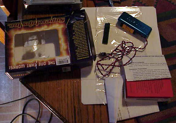
Contents of the kit
REMOVE THE KEY FROM THE IGNITION
Disconnect negative battery terminal

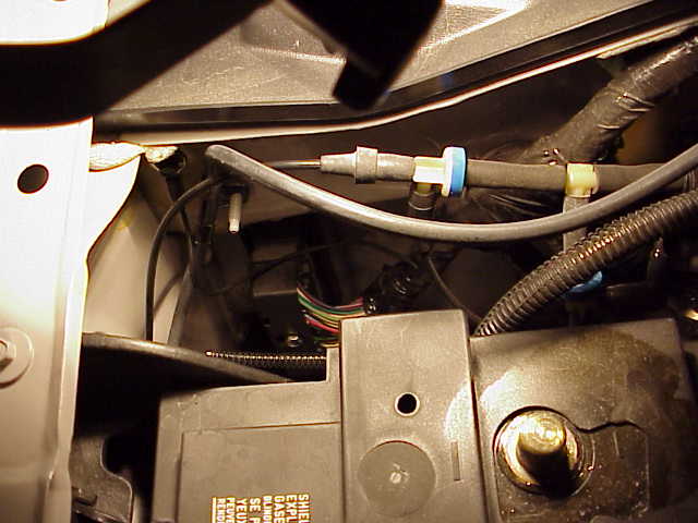
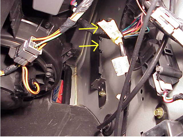
Use 10 mm socket to remove the bolt in the center of the Wire Plug above
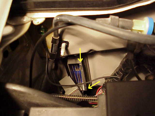
This is the front of the computer after the bolt is removed
-
Notice the little keyways on the computer point towards the drivers side -
You'll need to remember that when you replace the computer.
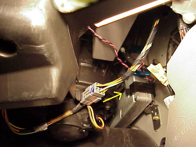
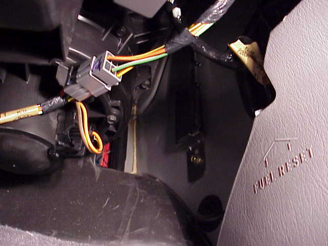
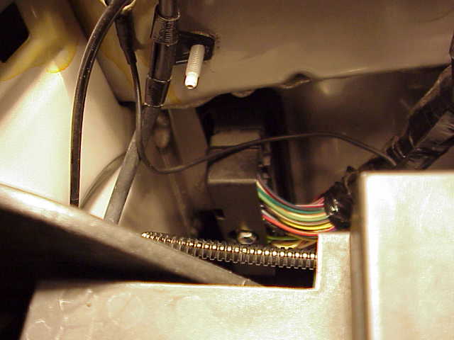
This is a shot under the passenger side kick panel after the
chip is installed but it
shows the location of the computer in the cab. Pull the little black clip
off and ease the computer out.
It is only held in place by the firewall gasket at this point.
Notice the lip on the bracket, you will want to bend the upper
2 parts of the lip out of the way
so they don't force the Superchip away from the computer after installation.
The easy way to bend them is to remove the bracket from the truck so you can get
some leverage on the bracket.
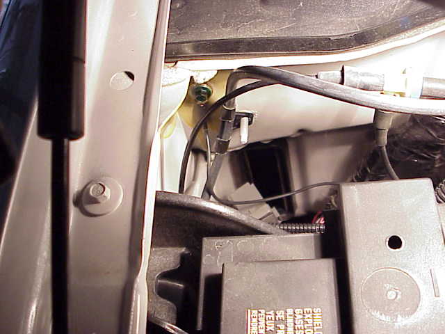
View from engine compartment looking down at battery and
firewall
Computer is missing - plug is dangling in front of hole
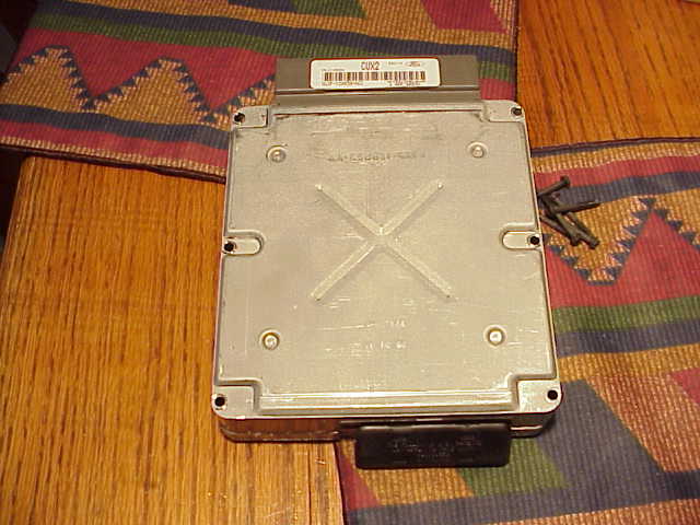
Computer
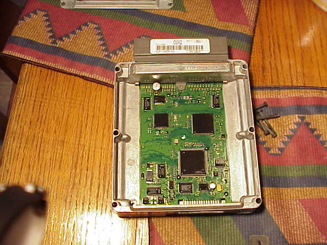
Top cover removed
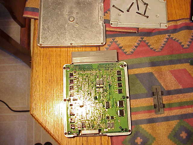
Bottom Piece just falls off after you remove the 6 screws.
Taking the computer apart makes cleaning the contacts MUCH easier since you can
get
good access to both sides of the edge connector..
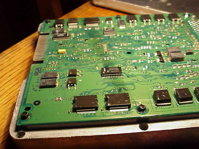
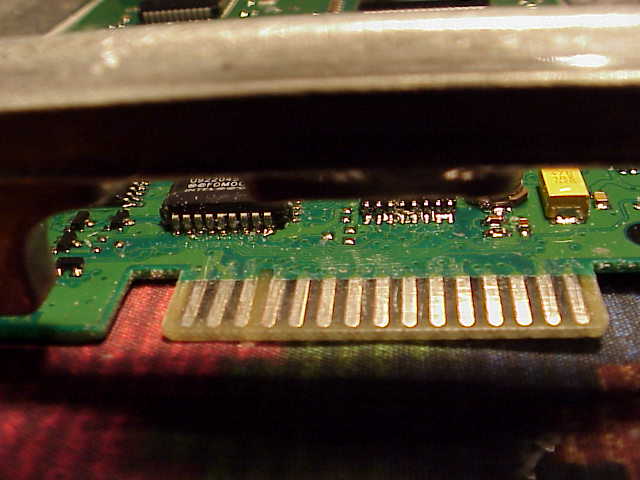
The shiny drops on the chips are big gobs of Conformal Coating as Superchips calls it
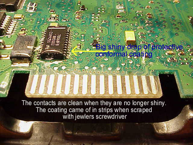
Clean contacts. I used a small screwdriver to remove 90% of the lacquer coating. Then I used the Scotchbrite pad to clean and buff the contacts smooth. If you use a screwdriver and work carefully you should be able to see the coating peel off in strips.
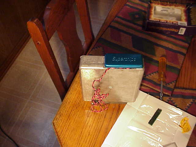
Assembled and ready to duct tape and slide back in...
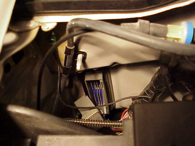
View from engine compartment of computer with plug removed

Computer slid back in place, the black clip and the firewall gasket are all that holds it in.
Red and black twisted pair is the flip switch wires. I
had elaborate plans for the switch but already
realized I will never switch it
so I will probably just coil it up next to the computer and zip tie it.
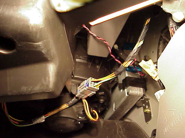
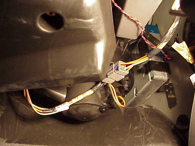
Make sure you carefully route the twisted pair wire so it is
not chafed by the lips on the bracket.
There is some evidence that incorrectly routed switch wires can cause radio
reception problems.
One cure is to pick a program and bundle the wire up and wire tie it near the
chip.
View of computer with plug attached
Working this close to battery be careful you don't knock
the negative
cable back against the battery post - Zap !!
All that is left is to reconnect the battery and start her up !!
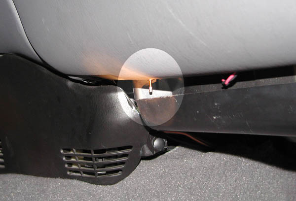
There is a great place to put the switch under the glove box. The
Superchips chip fits GREAT
No drilling and it is protected yet easily reachable.
The switch has 1 and 11 written on it and a notch on the
barrel of the toggle.
When the switch is nearest the notch that is the lower performing program.
I hope to add some pictures of the PSP chip soon as well...